U N D E R C O N S T R U C T I O N
Text by Arne Lüker
This article emerged from one of my unpublished scientific papers
The Quest for Pb-free piezoelectrics and ferroelectrics - a review
Lead zirconate titanate (PZT) based piezoelectric materials are well known for their excellent piezoelectric properties. However, considering the toxicity
of Pb and its compounds, there is a general awareness for the development of environmental friendly lead-free materials as regulated from the European Union.
Several classes of materials are now being considered as potentially attractive alternatives to PZTs for specific applications. In this paper, attempts have been
made to review the recent developments on lead-free piezoelectric and ferroelectric materials. In this context, perovskite systems such as barium strontium titanate,
bismuth sodium titanate, alkali niobates (ANbO3), etc., and non-perovskites such as bismuth layer-structured ferroelectrics are reviewed in detail.
From this study, it is concluded that some Pb-free compositions show stable piezoelectric and/or ferroelectric responses even though they do not match the overall
performance of PZT. The aim of this paper is to stimulate the growing research on this subject. This topic is of current interest to the researchers worldwide as
evidenced from the large number of recent research publications. This has motivated us to come out with a review article hoping it would motivate the researchers
already working in this area and to trigger the attention of researcher working on other topics of material sciences. In more or less short detours to linked
subjects we have made the effort to make this review more interesting to a larger field of researchers.
Introduction
Toxic effects of lead
Lead-free ferroelectrics with perovskite structure
BaTiO3 system
The (Bi0.5Na0.5)TiO3 system
The Bi0.5(Na0.5,K0.5)TiO3 system
The BNT-Ba(Ti,Zr)O3 system
The Bi(Na,K,Li)TiO3 system
The BNT-BKT-BT system
Alkali niobates
The KNbO3-NaNbO3 system
Non-perovskite structured lead-free ferroelectrics
Bismuth layer-structured ferroelectrics
Non-perovskites with lead-free tungsten-bronze structure
Remarks and limitations
Conclusions
References
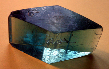 |
| Figure 1: Rochelle Salt crystal |
Piezoelectricity (pressure electricity) was discovered by Nobel laureates Pierre and Jacques Curie during their study of the effects of pressure on the generation
of electrical charge in crystals such as quartz, tourmaline, and Rochelle salt (figure 1) in 1880. Natural piezoelectric materials have relatively low piezoelectric
coefficients making them useless for commercial applications. A major breakthrough came with the discovery of the man-made perovskites (Pb,Zr)TiO 3 (PZT) and BaTiO 3 in the 1950s.
The family of these materials - named after the naturally occurring mineral perovskite CaTiO 3 - exhibit very high dielectric and piezoelectric properties.
To date, PZT (figure 2) is one of the most exploited and extensively used piezoelectric material. It is widely used in sensor and actuator devices, multilayered capacitors, as
hydrophones, etc. with an estimated market of tens of billions of dollars per year worldwide.
Ferroelectrics are a subclass of piezoelectrics, implying that all ferroelectrics are piezoelectric but not the other way round. Ferroelectricity was discovered by Joseph Valasek
in Rochelle salt in 1920 [1, 2]. The term ›ferro‹ describes the apparent analogy of ferroelectrics to ferromagnetism, viz. a permanent polarisation which can be
changed with an applied electrical or magnetic field in case of ferromagnetic materials (hysteresis curve). PZT and BaTiO 3 were the first commercial ferroelectric materials
used mainly for sonar systems to detect submarines and other military applications in the Second World War. Everyone who watched the 1981 German epic war movie "Das Boot" (engl. The Boat)
remembers the sharp ›chirp‹-sound when the allied Destroyers detected the submarine - that was the sound of the sonar system. Later on ferroelectrics conquered
the civil markets, in particular high capacitance, small volume capacitors in early televisions and radio circuits, as well as active elements for phonograph pick-ups,
accelerometers, and ultrasonic generators. Pb-based materials became the workhorses in these applications since they are easy to fabricate and show superior properties in a variety of
attributes like a very high dielectric constant, low loss, high tunability, large d 33- and d 11-values and so on [3].
However Pb-oxide, which is a component of PZT, is highly toxic and its toxicity is further enhanced due to its volatilization at high temperature particularly during calcination and sintering
causing environmental pollution during manufacturing.
Nowadays international efforts in removing toxic substances from everyday applications are increasing. The EU passed the »Waste Electrical and Electronic Equipment« (WEEE) and
»Restriction of the use of certain Hazardous Substances in electrical and electronic equipment« (RoHS) in 2003 [4]. While the WEEE regulates the disposal, reuse and recycling
of electronic equipment, the RoHS is a necessary requirement to ensure this can be accomplished safely without endangering the environment or people´s health. Mercury, cadmium, hexavalent chromium,
the flame-retardants Polybrominated biphenyl (PBB) and Polybrominated diphenyl ethers (PBDE) and, the focus of this work, Pb, have been identified as a primary risk during recycling, disposal or
just improper use.
|
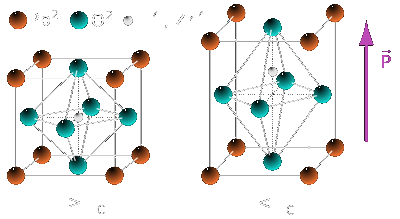
Figure 2: The PZT crystal structure above (left) and below (right) the phase transition temperature (TC); (left) cubic
paraelectric and (right) tetragonal ferroelectric. |
Therefore, as of June 2006, any products introduced to the open market may not include more than 0.1 wt.% of any one of these substances with the exception of cadmium where the limit is even lower
than 0.01 wt.%. Currently, an exemption is made for piezoelectrics though this is subject to regular review. New applications using these materials can only be introduced if
»elimination or substitution [...] is technically or scientifically impracticable, or where the negative environmental, health and/or consumer safety impacts caused by substitution are likely
to outweigh the environmental, health and/or consumer safety benefits« [4]. This would for example likely not hold for the use of Pb in newly invented consumer electronics.
It is therefore, desirable to find alternatives to the currently market-dominating Pb-containing piezoelectrics in all current or future applications. However, known Pb-free piezoceramics
are not yet good enough to replace Pb-containing materials. Despite many attempts by researchers in the past to develop alternative Pb-free materials their properties are nowhere near to the
PZT system, therefore, its use is still continued. Basically, the Pb-free systems are (i) perovskites, i.e., (Bi 0.5Na 0.5)TiO 3 (BNT), BaTiO 3 (BT),
KNbO 3, NaTaO 3, etc., (ii) non-perovskites, i.e., bismuth layer structured ferroelectrics (BLSF), and tungsten-bronze type ferroelectrics. While the perovskites are suitable
for actuators and high power applications, BLSF seems to be a candidate for ceramic filters and resonator applications.
The perovskite type ferroelectrics are promising candidates for Pb-free piezoelectric ceramics because its anisotropy in piezoelectric properties are large compared to other ferroelectrics.
A list of lead-free piezoelectric materials and their properties is presented in Table 1.
Table 1. Properties of some selected lead-free compositions
| Systems |
|
Compositions |
|
TC [°C] |
|
d33 [pC/N] |
|
K |
|
References |
| BT |
|
BaTiO3 |
|
130 |
|
140 |
|
1400 |
|
[128] |
| BNT |
|
(Bi0.5Na0.5)TiO3 |
|
310 |
|
64 |
|
302.6 |
|
[64] |
| BNT-BT |
|
(Na0.5Bi0.5)0.92Ba0.08TiO3 |
|
280 |
|
125 |
|
625 |
|
[27] |
| BNT-BT-Nb2O5 |
|
(Na0.5Bi0.5)0.92Ba0.08TiO3+xNb2O5 |
|
250 |
|
149 |
|
1230 |
|
[46] |
| BNT-BT-MnCO3 |
|
(Na0.5Bi0.5)0.92-Ba0.08TiO3+x mol% MnCO3 |
|
174 |
|
117 |
|
2300 |
|
[20] |
| BNT-BK-BT |
|
(Bi0.5Na0.5)TiO3-(Bi0.5K0.5)TiO3-BaTiO3
(1-3x)BNT-2xBKT-BT |
|
125 |
|
150 |
|
- |
|
[69] |
| BNT-BZT |
|
(Bi0.5Na0.5)TiO3-Ba(Ti,Zr)O3 |
|
244 |
|
147 |
|
8814 |
|
[64] |
| BNKLi-BT |
|
[Bi1-z(Na1-x-y-zKxLiy)]0.5BazTiO3
(BN-x/y/z)BN-0.15/0.75/0.02 |
|
210 |
|
205 |
|
1040 |
|
[26] |
| (K,Na)NbO3 |
|
(K0.5Na0.5)1-2yAEyNbO3
AE = Mg, Ca, Sr, Ba |
|
400 |
|
95 |
|
500 |
|
[116] |
The large piezoelectric response of PZT results from two factors. Primarily, the stereo-chemical activity of the 6s2 lone pair on the Pb-ion causes large structural distortions
from the cubic perovskite phase that results in strong coupling between the electronic and structural degrees of freedom [5]. Bi-based compounds have similar or larger levels of ion off
centering than Pb-based compounds, driven by the stereo chemically active 6s2 lone pairs on the Bi3+ ion. This leads to large ferroelectric polarizations. In most common ferroelectrics,
ion off centering is mainly contributed by the B-site cations to the ferroelectricity so as to increase the chemical bonding between their valence d-orbital and the surrounding oxygen 2p-orbital,
the so-called second-order Jahn Teller-effect [6]. In contrast to Pb, bismuth is non-toxic in its oxide forms; indeed, the active ingredient of the popular antacid (a mild drug which neutralizes
stomach acidity) is bismuth salicylate. Some of the toxic effects of Pb and its hazardous consequences on health are discussed in the next section
The important symptoms of Pb poisoning are fatigue, aches in muscles and joints, abdominal discomfort, etc. Some of the symptoms and signs of Pb poisoning are shown in Table 2. Patients with
poor dental hygiene may exhibit a blue line at the dental margin of the gums due to deposition of Pb-sulfide. Pb poisoning has long been considered as an environmental health hazard, for its adverse
effects on intellectual and neurological development [7-9].
Table 2: Symptoms and signs of lead poisoning after JN Gorden et al. [7]
| Mild |
|
Moderate |
|
Severe |
| Lethargy |
|
Anemia |
|
Convulsion |
| Anorexia |
|
Headache |
|
Coma |
| Abdominal discomfort |
|
Abdominal cramps |
|
Encephalopathy*) |
| Arthralgia**) |
|
Gingival lead line
Peripheral neuropathy |
|
Renal failure |
*) Encephalopathy means disorder or disease of the brain. In modern usage,
encephalopathy does not refer to a single disease, but rather to a syndrome of global brain dysfunction; this syndrome can be caused by many different illnesses.
**) Arthralgia literally means joint pain; it is a symptom of injury, infection, illnesses (in particular arthritis) or an allergic reaction to medication.
The main route of absorption in adults is the respiratory tract where 30-70% of inhaled Pb (mostly the inorganic form like oxides and salts) goes into the circulatory system. High blood lead levels
in adults are also associated with decreases in cognitive performance and with psychiatric symptoms such as depression and anxiety [10]. It was found in a large group of current and former inorganic
Pb-workers in Korea that blood Pb-levels in the range of 20-50 mg/dL were correlated with neuro-cognitive defects [11]. Increases in blood Pb-levels from about 50 to
about 100 mg/dL in adults have been found to be associated with persistent, and possibly permanent, impairment of central nervous system functions [12]. Pb has three
important biochemical properties that contribute to its toxic effects on humans. First, Pb being an electropositive metal has high affinity for enzymes, which are essential for the synthesis of hemoglobin.
Second, divalent Pb acts in a manner similar to calcium inhibiting mitochondrial oxidative phosphorylation thus reducing the intelligence quotient. Pb can also affect the genetic transcription of DNA by
interacting with nucleic acid binding proteins [13]. The most important initial aspect of management of Pb poisoning is the removal of the patient from the source of exposure [14] and second by using
chelating agents (EDTA) that form complexes with Pb and hence are excreted out [15-18].
An interesting historical remark: Since 1982, signs of a high exposure to Pb have been identified in the human remains of members of John Franklin's so-called lost expedition to the Arctic, 1845-8.
Franklins crew just turned mad at the end as a result of Pb poisoning. They left their ships behind and moved on with nothing else than empty dinghies and silver spoons towards the north pole.
Tinned food has been suggested as the source of this Pb. But there is a strong evidence that the primary source of this Pb was not tinned food, which was in widespread use in the Royal Navy at the time,
but the unique water system fitted to the expedition's ships [19].
In this review, an overview of current developments in various Pb-free piezoelectric and ferroelectric ceramics, and the effects of various dopants to enhance the piezoelectric and ferroelectric
properties is presented.
The perovskite-type (ABO3) ferroelectrics such as BaTiO3 (BT), (Bi0.5Na0.5)TiO3 (BNT), KNbO3, NaTaO3, etc. are well-known
lead-free piezoelectric materials. These ceramics show relatively large piezoelectric constants. However, the main drawbacks are generally low Curie temperatures (TC),
difficulties in poling treatments and/or low relative densities [20].
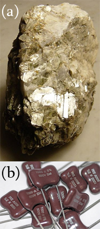 |
| Figure 3: Mica in its natural form (a) and capacitors made of mica (b) |
BaTiO3 (Barium titanate) was the first man-made perovskite. It was discovered independently in 1941 and 1944 in the United States, Russia and Japan. At least in the USA the research was
accelerated because of the Second World War. At that time, mica was used in most capacitors, but the German U-boats threatened the supplies of mica to the USA from South America [3]. Mica is a group
of sheet silicate (phyllosilicate) mineral which includes several closely related materials having highly perfect basal cleavage. All are monoclinic with a tendency towards pseudo-hexagonal crystals
and are similar in chemical composition. The highly perfect cleavage, which is the most prominent characteristic of mica, is explained by the hexagonal sheet-like arrangement of its atoms. Mica has the
unique combination of great dielectric strength, a uniform dielectric constant running from 6.4 to 9.3 with an average of 8.1 [21], capacitance stability, low power loss (high Q factor) and high
electrical resistivity. It is noted for its resistances to arc and corona discharge with no permanent injury. It is a complex hydrous silicate of aluminum, containing potassium, magnesium, iron,
sodium fluorine and/or lithium and also traces of several other elements. It is stable and completely inert to the action of water, acids (except hydro-fluoric and concentrated sulphuric), alkalies,
conventional solvents, oil and is virtually unaffected by atmospheric action.
However, the Germans forced the Americans to develop a new material for their capacitors and in 1941 Thurnmaurer and Deaderick at the American Lava Corporation filed the U.S, Patent No. 2,429,588 for
mixed BaO-TiO2 ceramics [22].
The high permittivities were found by measurements made at the Erie Resistor Company, with dielectric constants exceeding 1000, ten times greater than any other ceramic known at that time, such
as TiO2 (er=110).
|
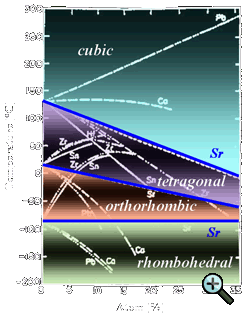
Figure 4: The effect of Sr-doping on the transition temperatures of BT, based on [79] |
The race to understand the nature of the dielectric anomaly in BaO-TiO2 ceramics continued, and in 1945 and 1946, von Hippel (USA), and Wul and Goldman (Russia) demonstrated ferroelectric
switching in these ceramics. The discovery of ferroelectricity in BaO-TiO2 ceramics was extremely important, as it demonstrated for the first time that ferroelectricity could exist
in simple oxide materials like perovskites [3].
BaTiO3 (BT) has a relatively high electromechanical coupling factor (k33) and has been partially used for piezoelectric applications such as sonar although its main use is
for capacitor applications.
It has the advantage of easy manufacture by various ceramic techniques. BT has a low Curie temperature (TC = 120 °C) causing the working temperature range of this ceramic narrow for
actual piezoelectric applications.
For ferroelectric devices it is an ideal candidate because its TC can be decreased with various dopants below room temperature (Fig. 4). The most prominent dopant is strontium (Sr).
Since that discovery, (Ba,Sr)TiO3 began to rock the military market
For that reason it is worthwhile to make a little detour to the subjects of phase shifters.
The most impressive change in the size of devices can be seen in phase shifters for radar technology (Fig. 5). Phase shifters are used to change the transmission phase angle (phase of S21) of a
network. Ideally phase shifters provide low insertion loss, high power handling, instantaneous phase change response, and approximately equal loss in all phase states.
While the loss of a phase shifter is often overcome using an amplifier stage, the less loss, the less power that is needed to overcome it. Most phase shifters are reciprocal networks, meaning that
they work effectively on signals passing in either direction (which comes in handy when you are designing a transmit/receive system like in a mobile phone).
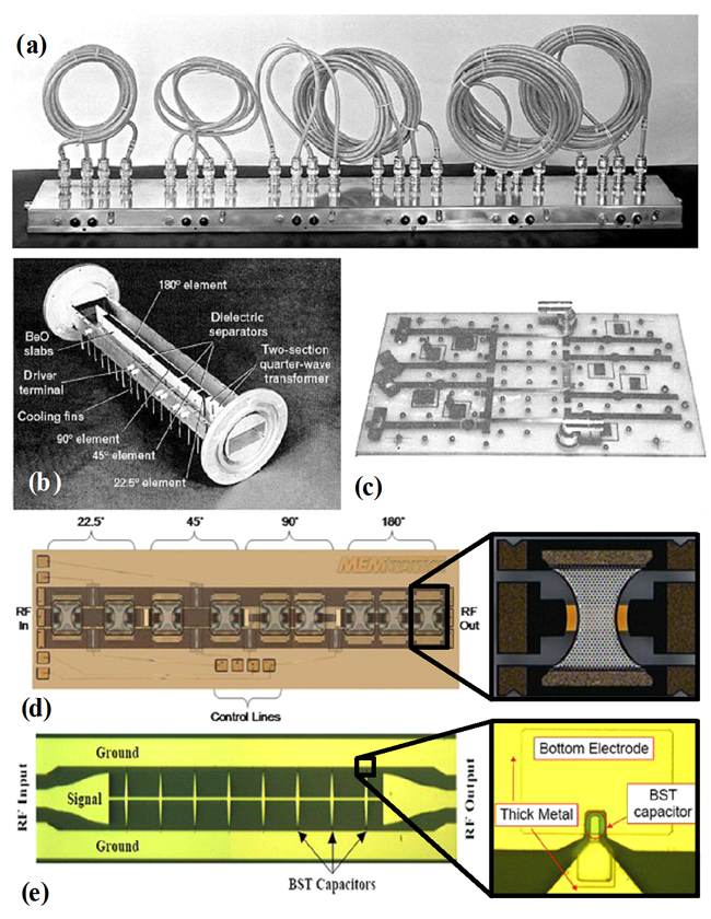 |
| Figure 5: Phase shifters for radar applications. (a) 1960 - an intermediate-frequency six-bit digital phase shifter. Each bit
consists of a length of coaxial cable that can switched into the signal path to produce the desired phase shift. (b) 1966 - a Westinghouse production model of a four-bit C-band ferrite phase
shifter, with the waveguide cover removed. (c) 1961 - a four bit low-loss hybrid L-band diode phase shifter. The stripline ground planes have been removed for clarity.
(d) 1995 - A MEMtronics phase shifter based on capacitive MEMS switches. (e) 2002 - A distributed phase shifter with voltage-tunable BST-varactors between the signal- and ground lines. |
Phase shifters can be controlled electrically, magnetically or mechanically. Phase shifters can be analog or digital. Analog phase shifters provide a continuously variable phase, perhaps
controlled by a voltage. Electrically controlled analog phase shifters can be realized with varactor diodes that change capacitance with voltage, or nonlinear dielectrics such as barium strontium
titanate (BST), or ferroelectric materials such as yttrium iron garnet. A mechanically-controlled analog phase shifter is really just a mechanically lengthened transmission line - as perfectly seen
in Figure 5a [23].
Currently, most phased array antenna systems rely on ferrite - Figure 5b [24] - or MEMS phase shifters - Figure 5d [25]. Ferrite phase shifters are slow to respond to control signals and
cannot be used in applications where rapid beam scanning is required. MEMS (micro-electro-mechanical systems) phase shifters have much faster response speeds (measure in milliseconds), however their
major drawback is that they have high losses at microwave and millimeter-wave frequencies. Other disadvantages with MEMS phase shifters is that they have limited power-handling capability (perhaps 100 mW)
and they may need expensive packaging to protect the movable MEMS bridges against the environment. MEMtronics developed phase shifters based on their own proprietary low-loss capacitive MEMS switches
to enable passive high performance phased array antennas from X-band through Ka-band and beyond. The most important features of these phase shifters are their very low insertion loss, negligible
power consumption (10s of nanojoules per switch cycle), and high linearity (third order intercept points exceeding +66 dBm). The chip size is 1.7mm x 5.4mm. Figure 5e shows a newly proposed device
topology by Robert A. York et al. [26]. Their approach is to periodically load a coplanar waveguide transmission line with tunable BST parallel plate capacitors. This new process provided 240° phase
shift with an insertion loss of only 3 dB at 10 GHz at room temperature with only 17.5 Volts. The circuit has demonstrated a record figure of merit 93°/dB at 6.3 GHz and 87°/dB at 8.5 GHz at room
temperature.
Actually this approach is a mixture of the ferroelectric phase shifter and MEMS phase shifter technology since it uses both the advantages of these technologies. It combines the low-loss properties
of BST at microwave frequency with the distributed transmission line philosophy of the MEMS phase shifter which provides wide bandwidth and ease of design.
PIN diodes can also be used to make very low-loss phase shifters, as seen in figure 5c [27], but who wants to deal with thousands of devices that are controlled by current, not voltage?
(Bi0.5Na0.5)TiO3 (BNT) is one of the important lead-free piezoelectric materials with perovskite structure discovered by Smolenskii et al. in 1961 [28].
(Bi0.5Na0.5)TiO3 exhibits strong ferroelectric properties with a large remnant polarization, Pr = 38 µC/cm2, and a high Curie temperature,
TC = 320 °C,. Therefore it has been considered for lead-free piezoelectric ceramics as an alternative to the widely used lead-based piezoelectric materials.
The main drawback of this material is its high conductivity, consequently giving problems in the poling process. In addition, BNT ceramics need high sintering temperature (>1200 °C) to obtain
densely packed ceramic. However BNT is considered to be a promising candidate for lead-free piezoelectric ceramics with balanced ferroelectric properties. In the following sections we discuss the
effect of various dopants on BNT ceramics.
Effect of dopants on BNT ceramics
For the pure BNT system, d33 lies in the range of 57- 64 pC/N as discovered by researchers pointed out in Table 3. The large piezoelectricity is expected in the BNT-based solid solutions
with a morphotropic phase boundary (MPB). It has been reported that BNT-based compositions modified with BaTiO3, BiKTiO3, NaNbO3, BiFeO3, MnO2,
Sc2O3, La2O3, CeO2, etc. [29-42] showed improved properties and easier treatment in the poling process when compared with pure BNT ceramics.
Table 3: Properties of the BNT system
| Composition |
|
Density [g/cc] |
|
d33 [pC/N] |
|
tand [%] |
|
K |
|
TC [°C] |
|
References |
| (Bi0.5Na0.5)TiO3 |
|
5.32 |
|
64 |
|
1.752 |
|
302.6 |
|
310 |
|
[60] |
| (Bi0.5Na0.5)TiO3 |
|
- |
|
57 |
|
0.011 |
|
240 |
|
450 |
|
[40] |
| (Bi0.5Na0.5)TiO3 |
|
- |
|
61 |
|
4.11 |
|
467 |
|
- |
|
[43] |
- Effect of La2O3: In order to improve the piezoelectric properties, Herabut and Safari [44] studied the effect of La as an additive and concluded that the d33
value increases from 64 to 92 pC/N for BNT doped with 6 mol% lanthanum oxide (Table 4). The piezoelectric properties were diminished once the doping level is beyond 2 at.% La. This is due to a phase
distortion from the rhombohedral to the pseudo-cubic phase. Furthermore, the dielectric constant and dissipation factor at the Curie point decrease when the amount of La doping in BNT increases.
Table 4: Effect of dopants on the BNT system
| Composition |
|
d33 [pC/N] |
|
tand [%] |
|
K |
|
TC [°C] |
|
References |
| (Bi0.5Na0.5)(1-1.5x) LaxTiO3 |
|
92 |
|
0.04 |
|
223 |
|
- |
|
[40] |
x = 1 |
|
80 |
|
0.015 |
|
375 |
|
370 |
x = 1.72 |
|
91 |
|
0.04 |
|
550 |
|
345 |
x = 2 |
|
89 |
|
0.033 |
|
495 |
|
335 |
x = 3 |
|
- |
|
0.036 |
|
770 |
|
365 |
| [Na0.5(1-x)Bi0.5(1-x)](Ti(1-x)-Nbx)O3 |
|
|
|
|
|
|
|
|
|
[43] |
x = 0.01 |
|
80 |
|
5.60 |
|
637 |
|
- |
x = 0.02 |
|
88 |
|
5.90 |
|
624 |
|
- |
x = 0.03 |
|
60 |
|
5.96 |
|
754 |
|
- |
x = 0.04 |
|
50 |
|
6.26 |
|
753 |
|
- |
x = 0.05 |
|
32 |
|
5.40 |
|
801 |
|
- |
- Effect of NaNbO3: Li et al. prepared lead-free bismuth sodium titanate-sodium niobate (BNT-NN), [Na0.5(1-x)Bi0.5(1-x)](Ti(1-x)-Nbx)O3
ceramics using conventional ceramic technique [45]. They concluded that d33 increases from 64 to 88 pC/N for 2 mol% of NaNbO3 and then decreases gradually. However, the dielectric
constant increases gradually with increase in NaNbO3 content. This is attributed to the co-effect of the soft additive Nb5+ ion doping at B-site and hard additive Na+
ion doping at A-site. However, with further doping content of NaNbO3 (x = 0.03-0.05), the piezoelectric properties decreased, which may be the result of the dominant doping of Na+
ion shown in Table 4 [43].
- Effect of BaTiO3: BNT-BaTiO3 (BNBT) shows the existence of a rhombohedral-tetragonal MPB. Takenaka reported that BNT-based solid solutions with a rhombohedral-tetragonal
MPB compositions showed higher piezoelectric and pyroelectric properties when compared with unmodified BNT ceramics [46]. It has been reported by Wang et al. [47] and Li et al. [48] that
the composition near the MPB has relatively large piezoelectric properties (Table 5). They came to the conclusion that an addition of BaTiO3 (6 mol% or 0.06) increases the d33
value (d33 = 129 pC/N) compared to pure BNT (d33 = 64 pC/N) [49-51].
Table 5: Properties of the BNT-BT system
| Composition |
|
d33 [pC/N] |
|
tand [%] |
|
K |
|
TC [°C] |
|
References |
| (Na0.5Bi0.5)0.94Ba0.06TiO3 |
|
125 |
|
1.3 |
|
625 |
|
288 |
|
[25] |
| (Na0.5Bi0.5)0.92Ba0.08TiO3 |
|
125 |
|
- |
|
- |
|
280 |
|
[51] |
| (1-x) (Na0.5Bi0.5)TiO3 - x BaTiO3 |
|
|
|
|
|
|
|
|
|
[46] |
x = 0.02 |
|
78 |
|
1.73 |
|
402 |
|
- |
x = 0.04 |
|
87 |
|
2.07 |
|
445 |
|
- |
x = 0.06 |
|
122 |
|
1.79 |
|
601 |
|
- |
x = 0.08 |
|
112 |
|
2.04 |
|
841 |
|
- |
x = 0.1 |
|
94 |
|
2.39 |
|
764 |
|
- |
| (Na0.5Bi0.5)TiO3-6BaTiO3 |
|
117 |
|
2.5 |
|
776 |
|
- |
|
[48] |
- Effect of Bi2O3 ⋅ Sc2O3: The dielectric, piezoelectric, and ferroelectric properties of the BNT-based solid solutions
(1-x)(Bi0.5Na0.5)TiO3-x(Bi2O3⋅Sc2O3)0.5 were also investigated from the view point of a new group of
lead-free piezoelectric ceramics (Table 6) [52].
Table 6: Properties of the (1-x)(Bi0.5Na0.5)TiO3-x(Bi2O3⋅Sc2O3)0.5 system
| Composition |
|
d33 [pC/N] |
|
tand [%] |
|
K |
|
TC [°C] |
|
References |
| (Bi0.51Na0.49)Sc0.02Ti0.98O3 |
|
74.7 |
|
5.11 |
|
431 |
|
358 |
|
[49] |
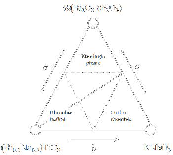 |
| Figure 6: Phase relation between (Bi0.5Na0.5)TiO3, KNbO3 and (Bi2O3⋅Sc2O3)0.5 [30] |
The effects of modified Bi3+ ions on the dielectric, piezoelectric, and ferroelectric properties for a pseudo-three-component system
a(Bi0.5Na0.5)TiO3-bKNbO3-c(Bi2O3⋅Sc2O3)0.5
(for a, b and c see figure 6) were studied and it was concluded that the Bi3+ ion has an effect on the coercive field, Ec [53]. Ec increases
when the amount of modified Bi ions is increased thus making poling difficult. On the other hand, the coercive field decreases when the amount of modified Bi ions is decreased;
making poling easier and k33 is slightly higher. Hence they can be used as superior lead-free or low lead content piezoelectric materials because the poling process stands a
better chance of success compared with non-modified BNT ceramics. Figure 6 shows the phase relation between (Bi0.5Na0.5)TiO3, KNbO3, and
(Bi2O3⋅Sc2O3)0.5 of this pseudo-three component system.
- Effect of La, Nb, Co: Influence of non-stoichiometry and doping on the piezoelectric properties and structure of BNT-BT based solid solutions near the MPB were studied by
Chu et al. [49]. Their preliminary research has indicated that cerium oxide is an effective additive for BNBT ceramics for the development of the BNT lead-free system [54].
From Table 7, they concluded that similar to PZT-based ceramics, Nb5+ can be seen as soft additive which leads to the enhancement of the piezoelectric constant, dielectric constant,
dielectric loss, etc. The B-site doping with Co3+ (hard additive) in this system enhanced the compositional inhomogeneity, which results in the multiphase character over a
relatively wide temperature range. The Piezoelectric coefficient, d33 of BNBT6-La and BNBT6-La-Nb, in which La3+ is added, is enhanced. These phenomena are like soft doping
in the case with PZT-based ceramics. Since La3+ has an ionic radius of 1.06 Å , it will substitute Bi3+ at the A-site because it has a similar ionic radius (the ionic radius
of Bi3+ is 1.03 Å). This substitution will result in a distortion of the crystal structure which results in a reorientation of domains during the polarisation process thus increasing
d33. For BNBT6-Co, d33 goes up to 139 pC/N, which can be explained with the remarkable growth of grain size after Co3+ doping and the value decreases after La addition.
Table 7: Properties of dopants on BNT-BT system
| Composition |
|
d33 [pC/N] |
|
tand [%] |
|
K |
|
TC [°C] |
|
References |
| (Na0.5Bi0.5)0.92Ba0.08TiO3+xNb2O5 (NBBT83) |
|
149 |
|
3.90 |
|
1230 |
|
250 |
|
[46] |
| (Na0.5Bi0.5)0.92-xBa0.08TiO3+xCo2O5 (NBBT84) |
|
108 |
|
1.50 |
|
450 |
|
245 |
|
|
| (Na0.5Bi0.5)TiO3-6BaTiO3+La (BNBT6)+La |
|
125 |
|
4.50 |
|
1576 |
|
- |
|
[48] |
| (Na0.5Bi0.5)TiO3-6BaTiO3+Nb (BNBT6)+Nb |
|
118 |
|
4.60 |
|
1614 |
|
- |
| (Na0.5Bi0.5)TiO3-6BaTiO3+La-Co (BNBT6)+La-Co |
|
127 |
|
2.10 |
|
1284 |
|
- |
| (Na0.5Bi0.5)TiO3-6BaTiO3+La-Nb (BNBT6)+La-Nb |
|
135 |
|
2.30 |
|
1664 |
|
- |
| (Na0.5Bi0.5)TiO3-6BaTiO3+Co (BNBT6)+Co |
|
139 |
|
2.30 |
|
1200 |
|
- |
| (Na0.5Bi0.5)0.94-6BaTiO3+0.5mol%CeO2+0.25mol%La2O3 |
|
158 |
|
1.70 |
|
787 |
|
- |
|
[27] |
| (Na0.5Bi0.5)0.94-6BaTiO3+0.5mol%CeO2+0.5mol%La2O3 |
|
162 |
|
2.00 |
|
831 |
|
- |
|
|
| (Na0.5Bi0.5)0.94-6BaTiO3+0.5mol%CeO2+0.75mol%La2O3 |
|
65 |
|
2.40 |
|
310 |
|
- |
|
|
| (Na0.5Bi0.5)0.92-Ba0.08TiO3+xmol%MnCO3 |
|
160 |
|
- |
|
- |
|
243 |
|
[51] |
- Effect of La2O3 and CeO2: Some further enhancement in these properties was reported by adding La2O3 and CeO2. From Table 7, it could be concluded that
addition of equal amount of 0.5 mol% CeO2 together with 0.5 mol% of La2O3 increases d33 value from 129 to 162 pC/N. The dielectric constant also increases
from 625 to 831. It has been reported that CeO2 has the dual effect of improving the piezoelectric properties of BNBT-6 ceramics and decreasing the dissipation factor. Ce3+ has
a radius of 1.18 Å and substitutes Ba2+ at the A-site in the BNBT lattice and functions as a donor leading to some A-site vacancies.
Meanwhile, Ce4+ with a radius of 0.94 Å goes into the Ti4+ site (r = 0.74 Å) and changes the space charge. La2O3 - a typical soft additive
for PZT ceramics - is occupying the Bi3+ site or the Ba2+ site [27].
- Effect of Mn: The maximum value of the piezoelectric constant was 160 pC/N for BNBT doped with 0.56 mol% Mn at room temperature [55]. From the table 8, it can also be seen that with
an increasing amount of the dopant, the TC decreases rapidly. When the amount of Mn is lower than 0.56 mol%, the increase in piezoelectric properties is partly due to the decrease of
tetragonality of BNBT. Additionally, the incorporation of smaller cations in a normal perovskite structure causes the slack of the lattice and enhances the motion of 90° domains. When the amount of
Mn is exceeds 2.6 mol%, it supersaturates the lattice of BNBT and the excess of Mn ions are accumulated in the grain boundaries, resulting in a pinning effect of the domain.
Table 8: Properties of x mol.% Mn on (Na0.5Bi0.5)0.92Ba0.08TiO3 [55]
| Mn-Content |
|
d33 [pC/N] |
|
Qm |
|
kt [%] |
|
kp [%] |
|
TC [°C] |
| x = 0 |
|
125 |
|
210 |
|
45.3 |
|
15.1 |
|
280 |
| x = 0.56 |
|
160 |
|
51 |
|
62.2 |
|
15.9 |
|
243 |
| x = 2.6 |
|
110 |
|
250 |
|
42.5 |
|
17.2 |
|
236 |
| x = 2.97 |
|
40 |
|
70 |
|
28 |
|
13.2 |
|
233 |
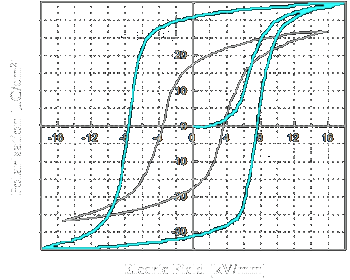 |
Figure 7: Hysteresis curves of (white) BNBT+0.56 mol% Mn and (turquoise) PZT |
Figure 7 shows the P-E hysteresis loop for BNBT doped 0.56 mol.% Mn (white) [55]. The coercive field (Ec) and remanent polarisation (Pr) are 3.54 kV/mm and 17 µC/cm2,
respectively. The turquoise curve represents a typical P-E hysteresis loop for PZT (30/70) [56] as a comparison. The coercive field is 7.9 kV/mm and the remanent polarization 30 µC/cm2.
At this point it is worthwhile to take a closer look at a ferroelectric hysteresis loop. The important characteristic of ferroelectric materials is polarisation reversal (or switching) by an applied
electric field. One consequence of the domain-wall switching in ferroelectric materials is the occurrence of the ferroelectric hysteresis loop (figure 8). The hysteresis loop can be observed experimentally
by using a Sawyer-Tower circuit [58]. At small values of the AC electric field, the polarization increases linearly with the field amplitude, according to relation
where cij [F/m] is known as the dielectric susceptibility of the material. This corresponds to segment AB in figure 8. In this region, the field is
not strong enough to switch domains with the unfavourable direction of polarisation. As the field is increased the polarisation of domains with an unfavourable direction of polarisation will start to
switch in the direction of the field, rapidly increasing the measured charge density (segment BC). The polarisation response in this region is strongly nonlinear and the former equation is no longer valid.
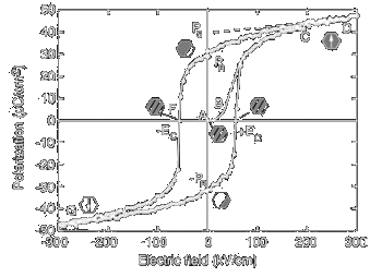 |
| Figure 8: Ferroelectric (P –E) hysteresis loop. The hexagons with the gray and black regions represent schematically repartition of two polarisation states in
the material at different fields. The symbols are explained in the text. The actual loop is
measured on a (111)-oriented 1.3 mm thick sol-gel Pb.Zr0:45Ti0:55/O3 film [57]. |
Once all the domains are aligned (point C) the ferroelectricity again behaves linearly (segment CD). If the field strength starts to decrease, some domains will back-switch, but at zero field the
polarisation is nonzero (point E). To reach a zero polarisation state the field must be reversed (point F). Further increase of the field in the negative direction will cause a new alignment of dipoles
and saturation (point G). The field strength is then reduced to zero and reversed to complete the cycle. The value of polarisation at zero field (point E) is called the remanent polarization, Pr.
The field necessary to bring the polarisation to zero is called the coercive field, Ec. The spontaneous polarisation Ps is usually taken as the intercept of the polarisation axis
with the extrapolated linear segment CD. (Strictly speaking, in polycrystalline materials the true spontaneous polarisation equal to that of a single crystal can never be reached. Therefore it is more
correct to speak of saturated rather than of spontaneous polarisation.) It should be mentioned that the coercive field Ec that is determined from the intercept of the hysteresis loop with the
field axis is not an absolute threshold field [59]. If a low electric field is applied over a (very) long time period the polarization will eventually switch.
The coercive field, spontaneous and remanent polarization and shape of the loop may be affected by many factors including the thickness of the film, the presence of charged defects, mechanical stresses,
preparation conditions, and thermal treatment. The tilt of the white loop for BNBT doped 0.56 mol.% Mn in figure 7 can be explained by the presence of a constant-valued capacitance layer at the
interfaces of the electrodes and the ferroelectric/piezoelectric film [60, 61]. This layer separates the bound charges that are due to the ferroelectric polarisation from the compensating charges on
the electrode. The depolarising field will thus be incompletely compensated even if the top and bottom electrodes are shorted.
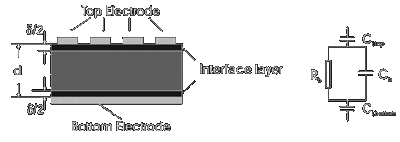 |
Figure 9: A schematic view of a ferroelectric device and its circuit diagram. |
The depolarizsng field Ed which is due to the presence of the constant value dielectric layer is given by
| Ed |
|
= |
|
- (P ⋅ d)/(ei ⋅ d) |
|
|
|
(Eq.: 2) |
where d and ei are the thickness and permittivity
of the constant value dielectric layer, and P and d are the polarisation and thickness of the ferroelectric layer. A simplified schematic of this arrangement is shown
in figure 9. Since the interface layer forms itself predominantly under the top electrode because it arises from surface contaminations and roughness of the ferroelectric/piezoelectric film,
nucleation or reaction layers at the film/electrode interfaces, or changes in the defect chemistry at the dielectric-electrode interfaces. The dependence of the inverse of the zero bias capacitance
density of the film to its thickness is often attributed to the presence of a constant-valued capacitance density, Ci/A, represented by the nonzero intercept, in series with the
thickness-dependent capacitance density of the bulk of the film. The apparent capacitance density at zero bias may then be expressed as
| A/Capp |
|
= |
|
A/Ci + A/CB |
|
= |
|
d/eie0 + (d-d)/eBe0 |
|
|
|
(Eq.: 3) |
where A is area of the top electrode, Capp the apparent capacitance, Ci the interfacial capacitance, CB
the bulk film capacitance, eB the film bulk permittivity, ei the interfacial
layer permittivity, e0 the permittivity of free space, d the total film thickness and d
the interfacial layer thickness [3]. The interface layer is often described as a dead layer because it gives no contribution to the ferroelectric/piezoelectric performance of the working device.
In other words, a ferroelectric device with a tilted P-E-loop has more losses than a material with a precipitous loop (see figure 7).
Zhang et al. investigated the microstructure and electrical properties of Bi-compensated BNT-BKT ceramics sintered at 1110-1170 °C [62, 63]. Increasing sintering temperatures enhanced the
grain growth, densification, and the piezoelectric and ferroelectric properties.
However, as the temperature was increased to 1170 °C, the piezoelectric properties degraded seriously. An MPB-like phase transition from tetragonal to rhombohedral symmetry was found in BNKT20 and
BNKT22 specimens sintered between 1150 and 1170 °C. Enhanced electrical properties were obtained for the BNKT22 samples sintered at an optimal temperature of 1150 °C, in which d33, Pr,
and K were 192 pC/N, 19.5 µC/cm2, and 1007, respectively.
- Effect of Strontium (Sr): Yoo et al. studied the variations of Sr substitution on lead-free Bi0.5(Na0.84K0.16)0.5TiO3 system [64]
and concluded that the crystal structure of the specimen moved from tetragonal to the tetragonal-rhombohedral MPB with 4-6 mol% Sr addition. The piezoelectric constant, d33 was 185 pC/N (Table 9).
They also studied the effect of La2O3 on the piezoelectric and dielectric properties of this lead-free system and concluded that with increasing amount of La2O3,
the density and dielectric constant increased up to 0.9 wt% La2O3 and decreased above it [65].
Table 9: Properties of Bi0.5(Na0.84K0.16)0.5TiO3-xSrTiO3 system
| Composition |
|
Density [g/cc] |
|
d33 [pC/N] |
|
K |
|
TC [°C] |
|
References |
| Bi0.5(Na0.84K0.16)0.5TiO3-xSrTiO3 |
x = 0.04 |
|
5.64 |
|
185 |
|
868 |
|
292 |
|
[64] |
x = 0.06 |
|
- |
|
205 |
|
- |
|
- |
0.94Bi0.5(Na0.84K0.16)0.5TiO3
-0.04SrTiO3+0.2wt%La2O3 |
|
5.75 |
|
215 |
|
768 |
|
320 |
|
[65] |
- Effect of NaNbO3: Li and his coworkers investigated a ternary system of BNT-BKT-NN and studied the effects of NN on the crystal structure, dielectric, ferroelectric, and piezoelectric properties
[45]. It can be found from Table 10 that the d33 value decreased with the amount of NaNbO3 and the relative low values were located at x = 8 mol%. This was due to a phase distortion
from rhombohedral to cubic phase. In contrast with BNT-NN binary system, the d33 of BNT-BKT-NN ternary system are higher.
Table 10: Properties of Bi0.5(Na0.5K0.5)TiO3-xNaNbO3 system [41]
| Composition |
|
d33 [pC/N] |
|
K |
|
TC [°C] |
| Na0.5Bi0.5TiO3-K0.5Bi0.5TiO3-NaNbO3 |
|
71 |
|
- |
|
- |
0.88Na0.5Bi0.5TiO3-0.12K0.5Bi0.5TiO3-NaNbO3
(NKBTN0) |
|
100 |
|
0.0299 |
|
575 |
| NKBTN8 |
|
100 |
|
0.0631 |
|
1237 |
It is generally known that BNT systems have a higher TC than BaTiO3 systems. Many scientists have been devoted to improving the piezoelectric properties of BNT-based ceramics.
One of them reported that Ba(Ti,Zr)O3 (abbreviated as BZT) system has a good piezoelectric constant equal to 236 pC/N at room temperature [66]. Hence a binary system of BNT-BZT was studied
and the properties at the MPB were investigated. Dense BNT-BZT ceramics (5.69-5.82 g/cm3) were obtained because the preparation processes were modified, in which BNT and BZT powders were
synthesized separately. For the BNT-BZT binary system, a high piezoelectric constant, d33 = 147 pC/N was obtained with a composition near the MPB. The pure BNT ceramic showed a high TC
value of 310 °C (Table 11). A little addition of BZT decreases the TC greatly.
Table 11: Properties of BNT-BZT system [64]
| Composition |
|
Density [g/cc] |
|
d33 [pC/N] |
|
K |
|
tand [%] |
|
TC [°C] |
| BNT |
|
5.32 |
|
64 |
|
302.6 |
|
1.752 |
|
310 |
| BNT-BZT3 |
|
5.76 |
|
79 |
|
345.6 |
|
1.765 |
|
236 |
| BNT-BZT6 |
|
5.72 |
|
107 |
|
844.6 |
|
2.185 |
|
236 |
| BNT-BZT9 |
|
5.72 |
|
147 |
|
881.4 |
|
2.636 |
|
244 |
| BNT-BZT12 |
|
5.69 |
|
112 |
|
788.7 |
|
2.980 |
|
259 |
However, when the addition of BZT exceeds 9 mol% there is a small increase in the TC. The reason for this small shift is not perfectly understood at present, but the BZT addition may
also influence the evolution of the sintered microstructure of the crystal, and thus the Curie temperature in addition to its chemical effect.
Lin et al. did further investigation on the BNT system by substituting Na+ in BNT by K+ and Li+ and finally invented Bi(Na,K,Li)TiO3 ceramics as a
new group of the BNT-based lead-free system [67]. Under this consideration, a new system of Bi(Na,K,Li)-BT multi component lead-free piezoelectric ceramics was also proposed [68]. Table 12 indicates
that the ceramics were well sintered at 1100-1150 °C for 2-3 h. The ceramics with a higher amount of K+ and a lower the amount of Li+ and Na+ have a relatively larger
piezoelectric constant (d33 = 143 pC/N). It can be concluded that with an increasing value of the K+/Li+ ratio, the piezoelectric constant increases. The amount of K+
also greatly influences the dielectric constant of the ceramics [67].
Table 12: Properties of Bi(Na,K,Li)TiO3-xNaNbO3 system [64]
| Composition |
|
d33 [pC/N] |
|
K |
|
tand [%] |
| [Bi0.5(Na1-x-y-zKxLiy)0.5]TiO3 |
| [Bi0.5(Na0.6K0.35Li0.05)0.5]TiO3 |
|
120 |
|
1753 |
|
5.7 |
| [Bi0.5(Na0.7K0.25Li0.05)0.5]TiO3 |
|
145 |
|
1276 |
|
4.1 |
| [Bi0.5(Na0.65K0.25Li0.1)0.5]TiO3 |
|
100 |
|
1109 |
|
4.9 |
| [Bi0.5(Na0.7K0.15Li0.15)0.5]TiO3 |
|
41 |
|
1179 |
|
- |
| [Bi0.5(Na0.75K0.05Li0.2)0.5]TiO3 |
|
51 |
|
800 |
|
- |
The [Bi1-z(Na1-x-y-z)KxLiy)0.5]BazTiO3 (BN-x/y/z) multicomponent lead-free piezoelectric system proposed by Lin et al.
were prepared by conventional ceramic techniques and their electrical properties were studied [68] (Table 13). The piezoelectric constant d33 has a maximum value of 178 pC/N at x = 0.15.
The maximum values of d33 (198 pC/N) of the BN-0.15/0.10/z ceramics occur at z = 0.02. The ceramics with x = 0.15-0.20 and z = 0.01-0.04 provide better piezoelectric properties, which may be
attributed to the compositions near the MPB where the number of spontaneous polarization directions increases [69]. However, the addition of Li significantly improves the sintering performance,
decreases the sintering temperature of BNT ceramics, and greatly assists in densification of BNT-based ceramics.
Table 13: Properties of Bi(Na,K,Li)TiO3-BaTiO3 system [24]
| Composition |
|
d33 [pC/N] |
|
K |
|
tand [%] |
| [Bi1-z(Na1-x-y-zKxLiy)]5BazTiO3, (BN-x/y/z) |
| BN-0.15/0.10/0.02 |
|
198 |
|
1170 |
|
3.7 |
| BN-0.15/0.075/0.02 |
|
205 |
|
1040 |
|
3.4 |
| BN-0.15/0.075/0.01 |
|
178 |
|
735 |
|
3.1 |
| BN-0.10/0.075/0.01 |
|
130 |
|
550 |
|
2.1 |
Barium titanate, BaTiO3 (BT), and potassium bismuth titanate, Bi0.5K0.5TiO3 (BKT) are well-known lead-free piezoelectric materials with a tetragonal phase.
The phase relation of the BNT-BT-BKT system is shown in Fig. 10. Takenaka and Sasaki et al. reported the binary systems of BNT-BT and BNT-BKT piezoelectric ceramics respectively [25, 26, 70].
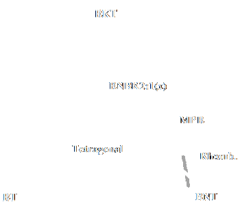 |
| Figure 10: Phase relation between (Bi0.5Na0.5)TiO3-BaTiO3-(Bi0.5K0.5)TiO3 (BNBK) system. |
Li et al. have demonstrated that preferred piezoelectric properties have been obtained by adding BKT and BT into BNT to form a BNT-BKT-BT ternary system [71]. They also investigated a
(1-3x)BNT-2xBKT-xBT ternary system by keeping the BKT and BT ratio constant (Table 14).
A conventional ceramic fabrication technique was used to prepare these materials. The piezoelectric and dielectric properties were also reported [73]. They concluded that the dielectric constant
and d33 increases with increasing x, reaches a maximum value of 150 pC/N at x = 0.035 and then decreases. These observations demonstrate that the compositions near the MPB have
relatively high piezoelectric and electromechanical activities due to the increase in the number of possible spontaneous polarization and to the coexistence of rhombohedral and tetragonal phases.
Li et al. prepared (1-5x)BNT-4xBNT-xBT ceramics by conventional ceramic fabrication technique [48]. The piezoelectric and ferroelectric properties of these ceramics were
studied. They came to the result that the piezoelectric constant d33 attains a maximum value of 149 pC/N at x = 0.03. This property demonstrates again that compositions near the MPB have
relatively high piezoelectric activities.
Lead-free piezoelectric ceramic 0.90(Bi0.5Na0.5)TiO3-0.05(Bi0.5K0.5)TiO3-0.05BaTiO3 (abbreviated as BNT-BKT-BT5) has been
used recently as the driving element in a cymbal actuator with titanium end caps. It was found that the lead-free ceramic cymbal actuator has reasonable piezoelectric coefficients and low density.
Hence its performance was comparable to those fabricated using hard PZT ceramic [72].
Table 14: Properties of Bi(Na,K)TiO3-BaTiO3 system
| Composition |
|
d33 [pC/N] |
|
References |
Na0.5Bi0.5TiO3-K0.5Bi0.5TiO3-BaTiO3
(1-3x)NBT-2xKBT-xBT
(x = 0.01, 0.02, 0,025, 0.03, 0.035, 0.04) at x = 0.035
|
|
150 |
|
[69] |
(1-5x)NBT-4xKBT-xBT
(x = 0, 0.01, 0.02, 0,024, 0.028, 0.03, 0.032) at x = 0.03
|
|
145 |
|
[45] |
KNbO3-based ceramics
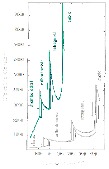 |
Figure 11: Phase transitions sequences in KNbO3 (white)[76] and BaTiO3 (turquoise) [77] for comparison |
B.T. Matthias discovered ferroelectricity in potassium niobate, KNbO3 in 1951 [74]. Alternative lead-free materials of the perovskite family with the general formula, ANbO3
(A = alkali metal) were proposed by researchers in the 1950s and 1960s [75]. KNbO3 (KN) has an orthorhombic symmetry at room temperature, and KN single crystals are known to have high
piezoelectric activities. It is known that KNbO3 and related compounds show a high Curie temperature (TC = 435 °C) and good piezoelectric properties.
(K,Na)NbO3 (abbreviated as KNN) is considered as one of the most promising candidates for lead-free piezoelectric ceramics. It is a solid solution of ferroelectric KNbO3 and
antiferroelectric NaNbO3, exhibiting very high Curie temperature (TC = 420 C), good ferroelectric properties (Pr = 33 µC/cm2), and large electromechanical
coupling factors [78]. The phase diagram for the KNN system is shown in Fig. 12. Regions labelled with Q, K, and L are monoclinic ferroelectric, M, G is orthorhombic ferroelectric; F, H and J are
tetragonal ferroelectric. Region P is orthorhombic antiferroelectric. At room temperature, MPBs lie at 17.5 %, 32.5 % and 47.5 % NN content. Notable is the almost composition independent
phase transition temperature between ferroelectric phases at ~200 °C and between ferroelectric and paraelectric phases at ~400 °C (in contrast to the composition dependent transition temperature of PZT).
Only small substitutions of sodium for potassium in NaNbO3 cause a transition to ferroelectric (Region Q) from the pure antiferroelectric sodium niobate (Region P) [79, 80].
The piezoelectric data for the air-fired samples are in the range of d33 = 80 pC/N and density of the sample is around 4.25 g/cc [81]. One of the main obstacles for the development of potassium
sodium niobates (KNN) as a commercial piezoceramic material by conventional method is the difficulty in processing and densification. Furthermore; the volatility of potassium oxide makes it difficult to
maintain stoichiometry. To optimize the processing conditions and to obtain reproducible properties, KNN ceramics were doped with suitable materials. Matsubara et al. [82] and Seo et al. [83]
found that the addition of CuO greatly enhanced the sinterability of KNN-based ceramics. CuO is often used because of its low melting point and the formation of a liquid phase.
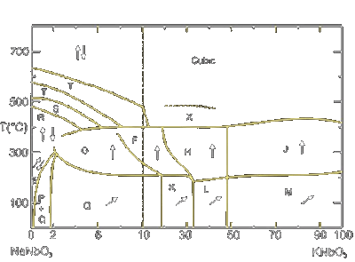 |
| Figure 12: Phase diagramm for the system KNbO3-NaNbO3 |
Park et al. [84] studied extensively the effect of CuO on KNN ceramics. They observed that an addition of CuO decreases the sintering temperature of KNN below 1000 °C, thus preventing the
Na2O evaporation. This improved the piezoelectric properties by increasing the polling efficiency. When a small amount of CuO was added, a dense microstructure with increased grain size
was developed. Liquid-phase sintering was considered to be responsible for the development of the dense microstructure.
The Cu2+ ion replaced the Nb5+ ion and produced an oxygen vacancy to maintain the charge neutrality. A defect dipole consisting of a Cu2+ ion and oxygen vacancy provided
the pinning effect, which eventually transformed the KNN ceramics into hard materials. TC and EC were slightly increased with CuO addition.
Bernard et al. [85] found that the densification of KNN ceramics can be improved by the addition of a small amount (from 0.5 to 4 mass%) germanate, which melts at around 700 °C. Germanate-modified
KNN ceramics can be sintered to high density (95.6% TD) at 1000 °C without degrading the piezoelectric properties.
Egerton and co-workers reported the electrical properties of KNN in which they indicated relatively low dielectric constants over a wide compositional range. Hence to achieve sufficient densification,
hot-pressed KNN ceramics (~ 99% of the theoretical density) have been reported to possess a high Curie temperature (TC = 420 °C), a large piezoelectric longitudinal response
(d33 = 160 pC/N), and a high planar coupling coefficient (kp = 45). KNN samples have been prepared by conventional air sintering in order to reach high densities over 95% which
yielded superior piezoelectric properties (d33 = 100 pC/N) than those obtained by the same method as reported previously [86]. It is important to note that KNN material prepared by spark plasma
sintering showed significantly higher dielectric and piezoelectric properties than those prepared by conventional method (K ~ 700 and d33 ~ 148 pC/N) [87, 88]
Recently, Saito et al. fabricated textured-based KNN ceramics by the reactive grain-growth method which produced d33 value as high as ~416 pC/N [87]. Comparisons of properties of
alkali niobates (ANbO3) obtained by different processing methods are given in Table 15.
Table 15: Comparison of properties of alkali niobates obtained by different processing methods
| Processing methods |
|
Density [g/cc] |
|
% TD |
|
d33 [pC/N] |
|
kp |
| Air-sintered (Jaeger-Egerton) K0.5Na0.5NbO3 |
|
4.25 |
|
94.24 |
|
80 |
|
0.36 |
| Air-sintered (Kosec) K0.5Na0.5NbO3 |
|
4.20 |
|
93.13 |
|
- |
|
0.23 |
| Air-sintered (Birol) K0.5Na0.5NbO3 |
|
4.30 |
|
95.3 |
|
110 |
|
0.39 |
| Hot-pressed (Jaeger-Egerton) K0.5Na0.5NbO3 |
|
4.46 |
|
98.98 |
|
160 |
|
0.45 |
| Hot-forged (Schultze) K0.5Na0.5NbO3+4mol% Ba |
|
4.28 |
|
94.90 |
|
115 |
|
0.37 |
| Reactive grain growth (Saito) |
|
- |
|
- |
|
416 |
|
- |
Effect of dopants on KNN-based ceramics: Potassium sodium niobate is a promising lead-free material with low dielectric constant and high electromechanical coupling coefficient.
However, it is difficult to prepare KNN ceramics with high density by conventional sintering technique. Sintering may be activated by the addition of Nb5+ or Mg2+ ions in the
crystal lattice thereby producing high-density samples [90 - 93].
- Effect of LiTaO3 and LiSbO3: The effect of incorporated LiTaO3 on the structure, phase transition behavior and electrical properties of the KNN system
have been studied very well [94-99]. It was established that Ta substitution for Nb, changes the properties of KNbO3 and the authors also demonstrated that small amounts of Ta for Nb could
enhance the piezoelectric properties of KNN ceramics [78, 100]. Saito et al. [101] also developed a lead-free system containing a blend of alkaline niobate (TC = 415 °C) based solid
solution with LiTaO3 (TC = 615 °C). This system gave good piezoelectric response with a d33 of 230 pC/N.
Addition of LiSbO3 to the above system increased the d33 to 373 pC/N [89]. Many authors have been studied the effect of LiSbO3 (LS) on pure KNN ceramics [102-104].
Yang et al. [102] studied the effect of LS on pure KNN ceramics and reported that increasing the LS content, the d33 and kp values of the ceramics initially increased,
and then began to decrease at higher LS concentration. In addition, dielectric study revealed that TC shifted toward the lower temperature regions and a normal ferroelectric KNN-based
ceramics changed to relaxor ferroelectric by increasing LS content. The KNN-LS ceramics are promising lead-free piezoelectric materials for electromechanical transducer applications. Effect of other
ions such as Ag, Nb, Ta, Bi, Cu, Ca, etc. and combinations of two or three these dopants on KNN-LS ceramics were also studied by many authors [105-117] and promising results were reported.
Wang et al. reported that an addition of Ag in KNN-LiTaO3 ceramics increases the Curie temperature (TC = 438 °C) and piezoelectric properties (d33 = 252 pC/N)
of the ceramic by normal sintering technique [118].
- Effect of alkaline earth ions: The effect of low amount of alkaline earth dopants, (0.5 at.%) Mg2+, Ca2+, Sr2+, and Ba2+ on KNN solid solution
synthesis, sinterability, and functional response of corresponding ceramics was also studied by different authors [119-122]. They were chosen on the basis of the similarity of their ionic radii to those
of K+ and Na+. Chang et al. [123] observed that adding Ca2+ and Sr2+ to KNN increase the cell parameters, promote densification, decrease the
phase transition temperatures, and improve the electrical properties.
However, adding Mg2+ to KNN can decrease the cell parameters and density, increase TC, and seriously deteriorate the electrical properties. Adding Ba2+ to KNN can
increase the cell parameters, decrease the density, decrease the phase transition temperatures, and also significantly deteriorate the electrical properties.
- Effect of BaTiO3: BaTiO3 is one of the typical ferroelectric materials showing large piezoelectricity, but its relative low TC limits the application.
However, by the addition of BaTiO3 to Na1-xKxNbO3, it could be anticipated that the solid solution would show a relatively high TC with
piezoelectricity comparable to BaTiO3 [124, 125].
Aurivillius type structure oxides with general formula Bi2An-1BnO3n+3, which consist of n-perovskite layers
[An-1BnO3n-1]2- sandwiched between bismuth oxygen sheets [Bi2O2]2+ are known under the name BLSF. The perovskite layer can
be a one, two, three, or more perovskite units thick. Each of these results in a separate structure type, but has the perovskite layer-bismuth oxide layer alteration [126]. Possible substitutions
into Bi-site of bismuth oxide layer by other p-cations that have a stereo-chemical active lone pair of electrons, such as Pb2+, Sb3+, and Te4+ have been reported.
Bi3NbTiO9 is an example of such compound because of its high TC (914 °C), however it posses very weak piezoelectric effects. The maximum d33 reported for any of these layer
structure compositions is 25 pC/N [81]. The family of BLSF is very attractive from the viewpoint of their applications as electronic materials such as dielectrics, piezoelectrics, and/or pyroelectrics.
BLSF are characterized by their low dielectric constant, high Curie temperature (TC), and large anisotropy in the electromechanical coupling factor. Therefore, the BLSF ceramics are seen
as superior candidates for lead-free piezoelectric applications for high TC piezoelectric sensors, filters, resonators, and/or pyroelectric sensors with large figures of merit [20].
- Bi4Ti3O12-based BLSF system: Bismuth titanate, Bi4Ti3O12, is a typical well-known BLSF. Concerning the anisotropy, Cross and Pohanka [127] reported that the BiT single crystal has good piezoelectricity.
However, it is difficult to measure piezoelectric properties on the BiT single crystal because of its thin structure. On the other hand, fully reliable piezoelectric properties of BiT ceramics have not
been reported because of some problems such as the low resistivity and the large coercive field. To solve these problems, Nb5+ and V5+ ions were doped into BiT ceramics to obtain higher
resistivity [15].
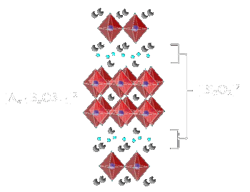 |
Figure 13: Aurivillius type structure oxides with general formula Bi2An-1BnO3n+3 |
- Bi3TiTaO9-based BLSF system : Bismuth layer-structured ferroelectrics of the type Bi3TiNbO9 and CaBi2Ta2O9
possess very high TC above 800 °C [81]. These data suggest that high mechanical quality factors (Qm) are obtained by BLSF materials with high TC making them suitable
for electromechanical transducer required to sense strains, vibrations, and noise under severe thermal conditions. By this concept, dielectric, ferroelectric, and piezoelectric properties of
Bi3TiTaO9 (BTT) based solid solution system with a high TC were also investigated [20]. The authors have studied that in the Sr-site substituted compositions,
there is a variation of the phase transition temperature with the ionic radius size and the amount of modifier, but no extra peaks in dielectric constant have been observed [128]. Figure 13 illustrates
the n = 2 phase of Bi3TiNbO9 as a representative of the Aurivillius phases, with the general formula {Bi2O2}-{A(n-1)B2O7}.
For this phase, Ti and Nb are statistically dispersed on the B site. The formula can be re-written as: {Bi2O2}-Bi(Ti,Nb)2O7. The separating motif for all
Aurivillius phases is a rock-salt Bi2O2 layer. For this example, Bi is also the A cation, but that need not be the case.
A number of ferroelectrics of potential commercial importance have the potassium tungsten-bronze AxB2O6 structure. Some examples are BaNb2O6, SrNb2O6,
SrxBa1-xNb2O6, AB2O6 type, etc. Piezoelectric ceramics with tungsten-bronze structure are potentially served as sensors in sensing
patches, single crystals for electro-optic uses, etc. Matsuo et al. studied the effect of doping Sr2-xCaxNaNb5O15 with La2O3
and concluded that a dielectric constant of 1662, Curie temperature of 298 °C, spontaneous polarization of 10.7 µC/cm2 and piezoelectric constant of 138 pC/N was obtained, respectively.
The piezoelectric properties of the SCNN-based ceramics indicate that they are good candidates for sensor applications [129-131]. The study investigating the electrical properties of dense lead-free
piezoelectric ceramics in the (1-x)Sr2NaNb5O15-xCa2NaNb5O15 (SCNN) system with x ranging from 0.05 to 0.35 has also
been reported. Ferroelectric and piezoelectric properties of SCNN greatly depended on the Ca content. The composition with x = 0.15 exhibited piezoelectric constant of d33 = 96 pC/N.
This study apparently indicates that lead-free SCNN piezoelectric ceramics have the potential for electromechanical applications.
Lead-free materials are of interests as new candidates to replace the widely used lead-based ceramics because of their pollution free environmental friendly character during the preparation process.
Hence, this research area is of current interest to researchers worldwide.
- BNT is considered to an excellent candidate for leadfree piezoelectric ceramics with a high TC of 320 °C, as well as relatively large remnant polarization, Pr of 38 µC/cm2 and a
coercive field, EC of 73 kV/cm. Still BNT cannot replace PZT due to its large coercive field and high conductivity. Hence researchers have investigated many dopants into BNT ceramics to
solve these problems.
- In addition to that, scientists have developed multicomponent systems, which have higher piezoelectric properties than binary systems. For example, BaTiO3, KNbO3 combined with
a rhombohedral compound to yield a high activity MPB system.
- The density of lead-free piezoelectric materials are approximately half of the density of PZTs; therefore, the effective specific piezo properties per unit weight of lead-free materials are double
their actual values when these materials have to be compared with PZTs. For example, a d33 value of 150 pC/N of a lead-free material is nearly equivalent to 280-300 pC/N of PZT material.
- Lead-free materials like BNT, NaNbO3, KNbO3, etc. were also developed simultaneously along with PZT in the 1950s. But due to the excellent piezoelectric properties exhibited
by the PZTs, the researchers preferred to work on the PZT system; hence, not much work was done on lead-free materials. Even though the initial results on PZT system showed lower piezo properties,
the values were largely enhanced after the discovery of MPB, addition of suitable dopants, etc., studied systematically. A similar systematic approach may be required for the enhancement of piezo
properties of lead-free materials at least very near to the level of PZTs.
Lead-free piezoelectric materials with excellent dielectric and piezoelectric properties belonging to the perovskite ferroelectric and bismuth layer-structured (BLSF) ceramics were investigated as
superior candidates to reduce environmental damages. The families of sodium potassium niobate and bismuth sodium titanate that come under the perovskite type ceramics seem to be suitable for actuator
and high power applications with a piezoelectric constant, d33 150 pC/N and a high Curie Temperature, TC > 200 °C. For high temperature applications (> 600 °C), bismuth-layered
compounds show good stability of properties and hence they serve as excellent candidates for piezoelectric sensors. In order to replace PZT systems, it is necessary that special features of each
lead-free material correspond to required piezoelectric properties for each application.
- J. Valasek, Phys. Rev. 15, 537 (1920); 17, 475-481 (1920). Piezoelectric and allied phenomena in Rochelle salt.
- J. Valasek, Phys. Rev. 19, 478-491 (1922); Piezo-electric activity of Rochelle salt under various conditions.
- Arne Lüker: Sol-Gel derived Ferroelectric Thin Films for Voltage Tunable Applications, ISBN 978-3-639-31446-5, VDM Publishing House Ltd., (2010)
- "EU-Directive 2002/95/EC: Restriction of the use of certain hazardous substances in electrical and electronic equipment (RoHS)," Official Journal of the European Union, 46[L37] 19-23 (2003).
- Hill NA, Rabe KM (1999) Phys Rev B 59:8759
- Halasyamani PS, Poeppelmeier KR (1998) J Chem Mater 10:2753
- Gordon JN, Taylor A, Bennette PN (2002) Br J Clin Pharmacol 53:451
- Barltrop D, Smith AM (1985) Postgrad Med J 51:770
- Rabinowitz MB, Wetherill GW, Kopple JD (1976) J Clin Invest 58:260
- Shih, RA; Hu, H; Weisskopf, MG; Schwartz, BS (2007). "Cumulative lead dose and cognitive function in adults: a review of studies that measured both blood lead and bone lead.". Environmental health perspectives 115 (3): 483-92
- Kosnett, MJ; Wedeen, RP; Rothenberg, SJ; Hipkins, KL; Materna, BL; Schwartz, BS; Hu, H; Woolf, A (2007). "Recommendations for medical management of adult lead exposure.". Environmental health perspectives 115 (3): 463-71
- Grant, L.D. (2009). "Lead and compounds". In Lippmann, M.. Environmental Toxicants: Human Exposures and Their Health Effects, 3rd edition. Wiley-Interscience. ISBN 0471793353.
- Goering PL (1993) Neurotoxicology 14:45
- Baldwin DR, Marshall WJ (1999) Ann Clin Biochem 36:267
- Kety SS (1942) J Biol Chem 142:181
- Leckie WJH, Tompsett SL (1958) Q J Med 27:65
- Aposhian HV (1983) Ann Rev Pharmacol Toxicol 23:193
- Graziano JH, Siris ES, Lolacono N, Silverberg SJ, Turgeon L (1985) Clin Pharmacol Ther 37:431
- William Battersby (2008) Identification of the Probable Source of the Lead Poisoning Observed in Members of the Franklin Expedition; Journal of the Hakluyt Society
- Takenaka T, Nagata H (2005) J Eur Ceram Soc 25:2693
- Weeks, J. R., The Dielectric Constant of Mica, Physical Review, vol. 19, Issue 4, pp. 319-322 (1922)
- H. Thurnmaurer and J. Deaderick, U.S, Patent 2,429,588, Oct. 21, 1947, filed Oct. 2 1941
- A. M.I. Skolnik, "Nonuniform Arrays," in Antenna Theory, pt. 1, R.E. Collin and F.J. Zuker, eds. (McGraw-Hill, New York, 1969), pp. 207-234.
- B. Wul W.J. Ince and E. Stern, "Computer Analysis of Ferrite Digital Phase Shifters," IEEE Int. Convention Record 14, pt. 5, New York, 21-25 Mar. 1966, pp. 32-38
- www.memtronics.com
- IEEE Microwave and Wireless Components Letters, Vol. 12, No. 7, July 2002
- J.L. Allen, D.M. Bernella, W.W. Carpenter, and W.P. Delaney, "Phased Array Radar Studies, 1 July 1961 to 1 July 1963," Technical Report 299, Lincoln Laboratory (20 Feb. 1963), DTIC #AD-41757
- Smolenskii GA, Isupov VA, Agranovskaya AI, Krainik NN (1961) Sov Phys Solid State 2:2651
- Takenaka T, Maruyama K, Sakata K (1991) Jpn J Appl Phys 30(9B):2236
- Shuvaeva VA, Zekria D, Glazer AM, Jiang Q, Weber SM, Bhattacharya P, Thomas PA (2005) Phys Rev B 71:174114
- Wang XX, Tang XG, Kwok KW, Chan HLW, Choy CL (2005) Appl Phys A 80:1071
- Zhao SC, Li GR, Ding AL, Wang TB, Yin QR (2006) J Phys D Appl Phys 39:2277
- Xiao DQ, Lin DM, Zhu JG, Yu P (2006) J Electroceram 16:271
- Peng CE (2006) Master's degree thesis, Tsinghua University, China, pp 66-75
- Hiruma Y, Watanabe T, Nagata H (2008) Jpn J Appl Phys 47:7659
- Takenaka T, Okuda T, Takegahara K (1997) Ferroelectrics 196:495
- Nagata H, Koizumi N, Takenaka T (1999) Key Eng Mater 169-170:37
- Wang XX, Chan HLW, Choy CL (2003) J Am Ceram Soc 86:1809
- Wang XX, Chan HLW, Choy CL (2003) Solid State Commun 125:395
- Zhou CR, Liu XY (2008) J Mater Sci 43:1016
- Mahboob S, Prasad G, Kumar GS (2007) J Mater Sci 42:10275
- Tian HY, Kwok KW, Chan HLW, Buckley CE (2007) J Mater Sci 42:9750
- Li YM, Chen W, Xu Q, Zhou J, Sun HJ, Xu R (2004) Mater Sci Eng B 112:5
- Herabut A, Sagari A (1997) J Am Ceram Soc 80:2964
- Li YM, Chen W, Xu Q, Zhou J, Sun HJ, Xu R, Liao MS (2005) J Electroceram 14:53
- Tatenaka T, Sakata K, Toda K (1990) Ferroelectrics 106:375
- Wang X, Chan H, Choy C (2003) Sol Stat Comm 125:395
- Li YM, Chen H, Xu Q, Zhou J, Gu X (2005) Mater Lett 59:1361
- Chu BJ, Chen DR, Li GR, Yin QR (2002) J Eur Ceram Soc 22:2115
- Wang TB, Gao M, Wang LE, Lu YK, Zhou DP (1987) J Inorg Mater 2:223
- Li HD, Feng CD, Yao WL (2004) Mater Lett 58:1194
- Nagata H, Takenaka T (1997) Jpn J Appl Phys 36(9B):6055
- Nagata H, Takenaka T (1998) Jpn J Appl Phys 37(9B):5311
- Sahoo B, Jaleel VA, Panda PK (2006) Mater Sci Eng B 126:80
- Zhou XY, Gu.HS, Wang Y, Li WY, Zhou TS (2005) Mater Lett 59:1649
- D. Bhattacharyya, A. Lüker, Q. Zhang and P. Kirby, Thin Solid Films, 518, 12, 3382 (2010)
- Taylor D V and Damjanovic D 1997 J. Appl. Phys. 82 1973
- Sawyer C B and Tower C H 1930 Phys. Rev. 35 269
- Burfoot J C and Taylor G W 1979 Polar Dielectrics and Their Applications (London: Macmillan)
- Tagantsev A K, Landivar M, Colla E and Setter N 1995 J. Appl. Phys. 78 2623
- Robels U, Calderwood J H and Arlt G 1995 J. Appl. Phys. 77 4002
- Zhang YR, Li JF, Zhang BP (2008) J Am Ceram Soc 91:2716
- Zhang YR, Li JF, Zhang BP, Peng CE (2008) J Appl Phys 103:074109
- Yoo J, Oh D, Jeong Y, Hong J, Jung M (2004) Mater Lett 58:3831
- Yoo J, Lee H, Lee B, Jeong Y, Hong J, Song H, Kwon J (2006) Sens Actuat A Phys 126:41
- Peng C, Li J, Gong W (2005) Mater lett 59:1576
- Lin DM, Xiao D, Zhu J, Yu P, Yan H, Li L (2004) Mater Lett 58:615
- Lin DM, Xiao D, Zhu J, Yu P (2005) Phys Stat Sol 202:89
- Lin DM, Xiao D, Zhu J, Yu P, Yan H, Li L, Zhang W (2004) Cryst Res Technol 39:30
- Nagata H, Yoshida M, Makiyuchi Y, Takenaka T (2003) Jpn J Appl Phys 42:7401
- Li YM, Chen W, Xu Q, Zhou J, Sun H, Liao M (2005) Ceram Int 31:139
- Lam KH, Wang XX, Chan HLW (2006) Sens Actuat A 125:393
- Li YM, Chen W, Xu Q, Zhou J, Gu X, Fang S (2005) Mater Chem Phys 94:328
- Jona F, Shirane G (1993) Ferroelectric crystals. Dover Publications Inc., New York, p 221
- Ringgaard E, Wurlitzer T (2005) J Eur Ceram Soc 25:2701
- C . A. Randall, N. Kim, J.-P. Kucera, W. Cao, and T. R. Shrout, J. Am. Ceram. Soc., vol. 81, no. 3, pp. 677-688, 1998.
- W. J. Merz, Phys. Rev., 76, 1221 (1949)
- Egerton L, Dillom DM (1959) J Am Ceram Soc 42:438
- M. Ahtee and A. M. Glazer, "Lattice parameters and tilted octahedra in sodium-potassium niobate solid solutions," Acta Crystallographica, Section A: Foundations of Crystallography, 32 434-45 (1976)
- M. Ahtee and A. W. Hewat, "Structural phase-transitions in sodium-potassium niobate solid-solutions by neutron powder diffraction," Acta Crystallographica, Section A: Foundations of Crystallography, 34[Mar] 309-17 (1978)
- Jaffe B, Jaffe H, Cook WR (1971) Piezoelectric ceramics, 1st edn. Academic Press, London
- Matsubara M, Kikuta K, Hirano S (2005) J App Phys 97:114
- Seo IT, Cho KH, Park HY (2008) J Am Ceram Soc 91:3955
- Park HY, Choi JY, Choi MK, Cho KH, Nahm S (2008) J Am Ceram Soc 91:2374
- Bernard J, Bencan A, Rojac T, Holc J, Malic B, Kosec M (2008) J Am Ceram Soc 91:2409
- Birol H, Damjanovic D, Setter N (2006) J Euro Ceram Soc 26:861
- Li JF, Wang K, Zhang BP, Zhang LM (2006) J Am Ceram Soc 89:706
- Zhang BP, Li JF, Wang K, Zhang H (2006) J Am Ceram Soc 89:1605
- Saito Y, Takao H, Tani T, Nonoyama T, Takatori K, Homma T, Nagaya T, Nakamura M (2004) Nature 432:84
- Kosec M, Kolar D (1975) Mater Res Bull 10:335
- Ichiki M, Zhang L, Tanaka M, Maeda R (2004) J Eur Ceram Soc 24:1165
- Gao DJ, Kwok KW, Lin DM, Chan HLW (2009) J Mater Sci 44:2466
- Bomlai P, Sukprasert S, Muensit S, Milne SJ (2008) J Mater Sci 43:6116
- Guo Y, Kakimoto K, Ohsato H (2005) Mater Lett 59:241
- Kim MS, Jeong SJ, Song JS (2007) J Am Ceram Soc 90:3338
- Rubio-Marcos F, Ochoa P, Fernandez JF (2007) J Eur Ceram Soc 27:4125
- Chang YF, Yang ZP, Hou YT, Liu ZH, Wang ZL (2007) Appl Phys Lett 90:232905
- Lin DM, Kwok KW, Chan HLW (2007) J Appl Phys 102:034102
- Dai Y, Zhang X, Zhou G (2007) Appl Phys Lett 90:262903
- Matsubara M, Yamaguchi T, Sakamoto W, Kikuta K, Yogo T, Hirano S (2005) J Am Ceram Soc 88:1190
- Saito Y, Takao H (2006) Ferroelectrics 338:17
- Yang Z, Chang Y, Liu B, Wei L (2006) Mater Sci Eng A 432:292
- Wu JG, Peng T, Wang YY, Xiao DQ, Zhu JM, Jin Y, Zhu JG, Wu L, Jiang YH (2008) J Am Ceram Soc 91:319
- Zhang SJ, Xia R, Shrout TR, Zang GZ, Wang JF (2006) J Appl Phys 100:104108
- Wu JG, Xiao DQ, Wang YY, Zhu JG, Wu L, Jiang YH (2007) Appl Phys Lett 91:252907
- Du HL, Liu DJ, Tang FS, Zhu DM, Zhou WC (2007) J Am Ceram Soc 90:2824
- Du HL, Luo F, Qu SB, Pei ZB, Zhu DM, Zhou WC (2007) J Appl Phys 102:054102
- Wu JG, Wang YY, Xiao DQ, Zhu JG, Pu ZH (2007) Appl Phys Lett 91:132914
- Wang YY, Wu JG, Xiao DQ, Zhu JM, Jin Y, Zhu JG, Yu P, Wu L, Li X (2007) J Appl Phys 102:054101
- Wu JG, Wang YY, Xiao DQ, Zhu JG (2007) Phys Status Solidi Rapid Res Lett 1:214
- Malic B, Bernard J, Bencan A, Kosec M (2007) J Eur Ceram Soc 28:1191
- Guo Y, Kakimoto K, Ohsato H (2004) Appl Phys Lett 85:4121
- Li HD, Shih WY, Shih WH (2007) J Am Ceram Soc 90:3070
- Park SJ, Park HY, Cho KH (2008) Mater Res Bull 43:3580
- Zhao P, Zhang BP (2008) J Am Ceram Soc 91:3824
- Zhao P, Tu R, Goto T (2008) J Am Ceram Soc 91:3440
- Wu JG, Xiao DQ, Wang YY (2008) J Am Ceram Soc 91:3402
- Wang Y, Wu J, Xiao D, Wu W, Zhang B, Wu L, Zhu J (2008) J Am Ceram Soc 91:2772
- Malic B, Bernard J, Holc J, Jenko D, Kosec M (2005) J Eur Ceram Soc 25:2707
- Guo Y, Kakimoto K, Ohsato H (2004) Solid State Commun 129:279
- Kosec M, Malic B, Bernard J, Holc J, Hrovat M, Bobnar V (2004) J Mater Res 19:1849
- Chang YF, Yang ZP, Chao XL, Zhang R, Li XR (2007) Mater Lett 61:785
- Chang Y, Yang Z, Wei L, Liu B (2006) Mater Sci Eng A 437:301
- Zhao S, Zhang L, Li G, Wang T, Ding A (2005) Phys Stat Sol 202:R22
- Lu YT, Chen XM, Jin DZ, Hu X (2005) Mater Res Bull 40:1847
- Yan H, Zhang H, Ubic R, Reece MJ, Liu J, Shen Z, Zhang Z (2005) J Adv Mater 17:1261
- Cross LE, Pohanka RC (1971) Mater Res Bull 6:939
- Gao X, Zhou Z, Xue J, Wang J (2005) J Am Ceram Soc 88:1037
- Huseyin Y, Susan T, Gary M (2003) J Electro Ceram 11:217
- Matsuo K, Xie RJ, Akimune Y, Sugiyama T (2002) J Ceram Soc Jpn 110:491
- Martin PD, Castro A, Millan P, Enez BJ (1998) J Mater Res 13:2565
[ back ]
|